Yuriy Skalskyy is N-iX Software Engineer with strong background in C++, .NET and Java web technologies, and a tech addict crazy about augmented reality and the Internet of things. Besides working for telecommunication project at N-iX, he often experiments with Arduino development board creating DIY home automation systems based on this multifunctional device. Here is his brief guide on how to assemble your own smart home solution.
Introduction
Do you remember that irritating feeling when you are lying in bed and suddenly realize that you forgot to turn off the light somewhere in your house? Have you ever thought about turning off iron just after departing from the bus stop? That’s all could be fixed by bringing a part of the Internet of things to your life. A simple solution allows you to save money by reducing heating when nobody is home and maintain ideal temperature and humidity. You can change light color and dim main light down right from your smartphone. In case of emergency, you may be informed about water leakage or fire and undertake measures to minimize the damage.
I came up with the idea of creating home automation system to complete the following set of goals:
- Electrical circuits control
- Lighting control
- Climat control
- Emergency gas and water switch
To make my system work I’m currently using quite wide and interesting stack of technologies: Arduino IDE with its language, Java, NoSQL, SVG, JavaScript, REST services and many more.
Hardware
- Arduino nano
- Sensors
- Switches
- Custom IR and power controls
General look
All WiFi components can communicate with x86 server directly through a local WiFi network, but separate network will be more secure solution.

Let’s look at the components in details:
- x86 computer
Nothing special is required. There is no need for powerful machine, just for a computer that can withstand short-term power failures, so any cheap netbook could be OK.
- Arduino commander
At the heart of the whole system there is a simple Arduino nano board + WiFi module that will be described below. It is working mostly as a proxy or router, transferring x86 server requests into components network and sending sensors info back to the server.
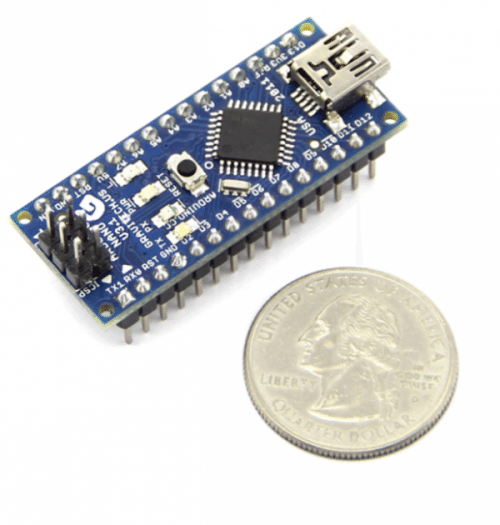
- Controlled switches and sensors are the same Arduino boards with additional stuff such as dimmers, servo controls or switches, as on the picture below:

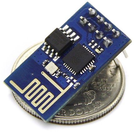
- For WiFi components I’m using ESP8266 board with Arduino and sensors or controls. It can be connected to a regular wifi router and supports WiFi standards and incoming connections.
Software
Most of the users haven’t got a static IP address. So the best solution is Dynamic DNS. It registers domain or subdomain address using dynamic IP and updating it after the user re-enters the network. There are lots of free DDNS services.

But DDNS could be an issue if you’re already behind a NAT. NAT server gets requests from different internal IPs and forwards it from one IP with different ports. So internet request from different computers of your network look like requests from one computer with different ports. In that case to access your computer you would need some external host with static IP or DDNS to make it work like proxy. Both server app and client should make outgoing connections there. You can create proxy on a local computer and use NAT Traversal technology, but still in most cases you would need a separate visible outside host to make it work.
To establish control over the system user have to open web app, where schematic plan will be displayed. Each room has its own ID and components. Setup and configuration is made via web UI. For demonstration I use SVG. Here are some code samples on how to create and manipulate SVG elements in JavaScript:

createSVGTag is used for creating SVG elements such as circles, lines, polygons, etc. The whole image is generated dynamically.

Here you can see the creation of area polygon in edit mode with draggable circles on the vertices. These are the hardcoded values, but I`m going to add some color styling with time.

It`s not a perfect event driven solution, and I still have a lot to work with.

All sensor states are updated using short polling to REST service and changing any control state causes simple request there. Here are some easy service methods.

Working with NoSQL is also very simple here. As they say “Keep it simple”. I’m using HyperGraphDB.

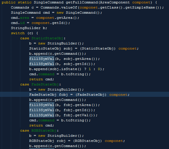
Another interesting approach is Commands Enumeration with commands sent to Arduino. It knows command length, parameters, and I think it’s cool. Check out this piece.
From Arduino side, the code is also pretty simple, reading data from serial, parsing strings, setting some state. You can check Capacitive Sensing Library which I use for my manual switches or ESP8266 arduino library for WiFi communications.
The communication between components could be very interesting. As I already mentioned on a diagram, I’m using UTP cable with 8 wires. Two of them are used for power supply, one for a lock state, another one for some kind of clock and the remaining 4 are used to post 4 bit value per cycle. Before continuing with this, I should mention that there are only 2 types of components sensors that send info to the network and controls which receive it. Commander is the only exception but let’s look on it as a 2 modules system. Sample scenario with collision could be:
- Writer1 checks lock state(it’s unlocked)
- Writer2 checks lock state(still unlocked)
- Writer1 writes signal to lock wire
- Writer2 writes signal to lock wire
- Writer3 checks lock state(it’s locked, sleep for a while)
- Readers found lock and waiting for clock wire value change
- Writer1 writes random 4 bit value and sleeps for a small random period
- Writer2 writes random 4 bit value and sleeps for a small random period
- Writers check the clock state and value in bus. Here are several scenarios:
- State already changed, release lock and sleep for a while
- Writer is the only one and the value is the same, write to clock and sleep while all possible writers in collision are checking the status.
- 2 or more writers and value1|value2=value3 then all writers release lock and sleep for random time
- 2 or more writers and value1|value2=value1 then Writer1 continue scenario b and writer2 sleeps for a random time
- value1=value2 rather rare mostly not because the values(only 16 variants for 4 bit) but random sleep periods.
- After Writer wakes up it checks again the value and clock to avoid e scenario, and begin writing useful information by 4 bit blocks, informing about the new block by clock wire state change. the ID of receiver is coded in first 4 blocks.
Another interesting moment here is that I use java-simple-serial-connector for serial communication between Java web app and Arduino. Everything is stored in git and build by maven.
Thanks for reading!